Train Mascon (Sony PlayStation 2)
Overview
 | Name | Train Mascon (Sony PlayStation 2) |
| Release date | October 31, 2002 | |
| Serial code | COTM-02001 | |
| Notes |
Supported software
Technical details
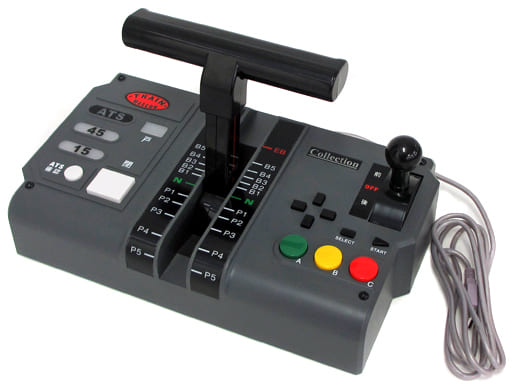
This controller has one handle (5 power notches and 8+emergency brake notches), a D-Pad and 7 buttons (Select, Start, A, B, C, Close, ATS). The A button can distinguish between “soft” and “hard” presses. In addition, the controller has four lamps: doors, ATS, 45 and 15.
Internally, it is a vendor-specific class device. The input data is compatible with HID, but the device does not provide a HID descriptor.
| Product name | Unavailable |
| Manufacturer | Unavailable |
| Vendor ID | 0x1C06 |
| Product ID | 0x77A7 |
| Serial number | Unavailable |
| USB standard descriptor | Download (from Multi Train Controller) |
| HID report descriptor | Download (recreated, not provided by actual device) |
Input
The controller sends reports to the host (PS2) formed by 4 bytes:
| Byte # | Data |
|---|---|
| 1 | 0x01 (fixed) |
| 2 | Reverser+handle |
| 3 | Buttons 1 |
| 4 | Buttons 2 |
The reverser+handle byte combines two values representing the state of the reverser and the power/brake handle. The handle notch is represented sequentially starting from 0x1 (Emergency), brake notches from highest to lowest, N and power notches from lowest to highest.
| Position | Value |
|---|---|
| Forward | 0x2X |
| Neutral | 0x0X |
| Backward | 0x1X |
The first button byte uses bits to represent the state of the physical buttons. 0 means that the button is released and 1 that it is pressed.
| Bit | Physical Button |
|---|---|
| 1 | ATS |
| 2 | Close |
| 3 | A (soft) |
| 4 | A (hard) |
| 5 | B |
| 6 | C |
| 7 | Unused |
| 8 | Unused |
The second button byte also uses bits to represent the state of the physical buttons.
| Bit | Physical Button |
|---|---|
| 1 | Start |
| 2 | Select |
| 3 | Up |
| 4 | Down |
| 5 | Left |
| 6 | Right |
| 7 | Unused |
| 8 | Unused |
Output
The controller supports receiving data via a control transfer to turn on/off the lamps. The USB setup packet is as follows:
| Data | Value |
|---|---|
| bmRequestType | 0x40 |
| bRequest | 0x50 |
| wValue | Lamp data |
| wIndex | 0x0 |
| wLength | 0x0 |
Changing wValue controls the lamps with the logic below.
- Door lamp: 0x0X is Off, 0x1X is On.
- Signal lamp: 0xX0 is Off, 0xX1 is ATS, 0xX2 is 45, 0xX3 is 15.